
Your Cart is empty
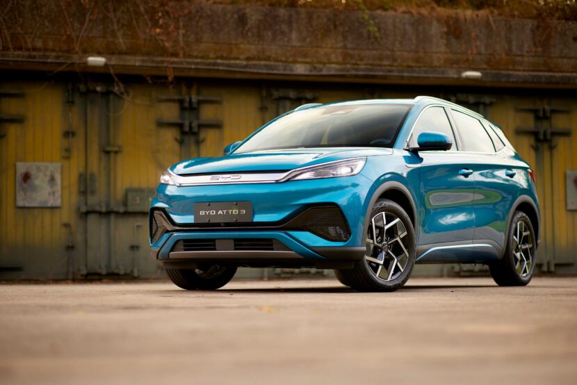
BYD ATTO 3 (e-Platform 3.0) U20B400 BIC5 CAN Communication Timeout Fault
Diagnostic Trouble Code (DTC) U20B400 indicates that the Battery Management System (BMS) has detected a CAN communication timeout involving Battery Information Collector 5 (BIC5). Workshop references for the BYD ATTO 3/Yuan Plus identify U20B400 specifically as the BIC5 CAN Communication Timeout fault.
BIC5 is part of the high-voltage battery monitoring system and communicates battery-monitoring information to the BMS through the battery CAN network. When expected communication from BIC5 is not received within the required time, the BMS can store U20B400.
Loss of communication with BIC5 may prevent the BMS from receiving reliable cell-voltage and battery-temperature information from the section monitored by BIC5. As a protective measure, the BMS may restrict charging, reduce available vehicle power, or disable high-voltage operation.
Symptoms
- High-voltage system warning displayed
- EV system warning displayed
- Reduced vehicle power
- Charging restricted or disabled
- DC fast charging unavailable or limited
- Vehicle may refuse to enter READY mode
- Missing BIC5 battery-monitoring data
- Missing or abnormal cell-voltage readings
- Missing or abnormal battery-temperature readings
- Multiple BMS communication DTCs
- Vehicle may enter a protective or fail-safe state
Possible Causes
- BIC5 CAN communication interruption
- BIC5 power-supply fault
- BIC5 ground fault
- Open CAN-H circuit
- Open CAN-L circuit
- Shorted CAN-H or CAN-L
- Damaged CAN wiring
- Loose BIC5 connector
- Corroded connector terminals
- Poor terminal contact
- Damaged battery communication harness
- BIC5 internal fault
- BMS communication fault
- CAN network integrity problem
- Water or moisture intrusion
- BIC5 software or configuration problem
Diagnosis
Begin with a BYD-compatible diagnostic scan tool and perform a complete scan of the BMS and battery-monitoring system.
Record all stored, pending, and historical DTCs before clearing the codes.
Determine whether U20B400 is:
- The only communication fault
- Accompanied by BIC5 operational faults
- Accompanied by BIC5 voltage-sampling faults
- Accompanied by BIC5 temperature-sampling faults
- Accompanied by communication faults from other BIC units
The presence of U20B400 together with P1A1000 or P1A2400 is particularly important because it may indicate that the BMS has lost reliable access to both voltage and temperature information from BIC5.
BIC5 Communication Status
Use the diagnostic tool to determine whether BIC5 is recognized by the BMS.
Check:
- BIC5 online/offline status
- BIC5 identification
- BIC5 communication status
- BIC5 voltage data
- BIC5 temperature data
- BIC5 diagnostic status
- Communication errors
If BIC5 is completely offline, inspect its power and communication circuits before replacing the module.
If BIC5 appears intermittently, investigate loose terminals, damaged wiring, connector problems, and CAN signal integrity.
BIC5 Power Supply Inspection
Loss of power to BIC5 can cause U20B400.
Inspect the applicable BIC5 power and ground circuits for:
- Correct supply voltage
- Stable power supply
- Correct ground connection
- Excessive voltage drop
- Loose terminals
- Corrosion
- Damaged wiring
- Moisture contamination
A BIC5 module without its required power supply cannot transmit CAN messages even when the CAN wiring itself is intact.
Power and ground measurements should be performed according to the applicable BYD service procedure.
CAN-H and CAN-L Inspection
Inspect the BIC5 CAN communication circuit.
Check:
- CAN-H continuity
- CAN-L continuity
- CAN-H for unwanted shorts to ground
- CAN-L for unwanted shorts to ground
- CAN-H for unwanted shorts to power
- CAN-L for unwanted shorts to power
- CAN-H and CAN-L for unintended shorting
- Connector terminal condition
- Harness damage
- Chafing
- Pin deformation
- Corrosion
- Water intrusion
The actual acceptable resistance and voltage values should be taken from the applicable BYD service information rather than relying solely on generic CAN specifications.
CAN Network Integrity
If BIC5 power and local wiring appear normal, investigate the wider battery CAN network.
Check whether the other BIC units are communicating normally.
For example:
- BIC5 offline while other BICs remain online may indicate a localized BIC5 circuit or module fault.
- Several BICs offline simultaneously may indicate a common communication, power, ground, or BMS network problem.
- Intermittent communication from multiple BICs may indicate a network-level fault.
A suitable CAN analyzer or oscilloscope can be useful when an intermittent communication fault cannot be identified through conventional continuity testing.
BIC5 Connector Inspection
Inspect the BIC5 connector carefully.
Look for:
- Loose terminals
- Backed-out pins
- Bent terminals
- Corrosion
- Oxidation
- Moisture
- Damaged seals
- Contaminated contacts
- Poor terminal tension
- Damaged connector housing
A connector problem can produce an intermittent U20B400 that temporarily disappears after vibration, temperature changes, or movement of the battery harness.
BIC5 Voltage and Temperature Data
If communication with BIC5 is restored, check its live data.
Verify:
- Individual cell voltages
- Cell-voltage differences
- Battery temperatures
- Temperature differences
- Battery current
- Battery voltage
- BIC5 status
- BIC5 communication status
If BIC5 communicates but reports abnormal voltage or temperature values, investigate additional BIC5 sampling faults.
Relevant faults include:
- P1A1000 — BIC5 Voltage Sampling Abnormality
- P1A2400 — BIC5 Temperature Sampling Abnormal
These codes can help distinguish a communication problem from a fault within BIC5’s measurement circuits.
BIC5 Module Diagnosis
If:
- BIC5 power supply is correct
- BIC5 ground is correct
- CAN-H and CAN-L wiring are correct
- Connectors are in good condition
- CAN network integrity is normal
but BIC5 remains offline, BIC5 itself may be faulty.
Follow the applicable BYD diagnostic procedure before replacing the module.
The BIC5 module should not automatically be replaced simply because U20B400 is stored.
BMS Diagnosis
If BIC5 communicates normally but the BMS continues to report U20B400, investigate the BMS side of the communication network.
Check:
- BMS CAN communication
- BMS connectors
- Battery communication harness
- CAN network integrity
- Related BIC communication DTCs
- BMS software or calibration
- Intermittent communication interruptions
If several BIC communication faults are present, the BMS or common battery communication network should receive particular attention.
Related DTCs
Check for related faults such as:
- P1A1000 — BIC5 Voltage Sampling Abnormality
- P1A2400 — BIC5 Temperature Sampling Abnormal
- BIC5 operational abnormality faults
- U20B000 — BIC1 CAN Communication Timeout
- U20B100 — BIC2 CAN Communication Timeout
- U20B200 — BIC3 CAN Communication Timeout
- U20B300 — BIC4 CAN Communication Timeout
- U20B500 — BIC6 CAN Communication Timeout
- U20B600 — BIC7 CAN Communication Timeout
- U20B700 — BIC8 CAN Communication Timeout
The U20B000–U20B700 series is documented as individual BIC CAN communication timeout faults.
Important Diagnostic Checks
A complete diagnosis should include:
- Full BMS DTC scan
- BIC5 communication-status check
- BIC5 power-supply testing
- BIC5 ground testing
- CAN-H inspection
- CAN-L inspection
- CAN wiring continuity
- CAN short-circuit testing
- Connector and terminal inspection
- CAN network integrity testing
- BIC5 voltage-data inspection
- BIC5 temperature-data inspection
- Battery communication harness inspection
- BMS communication testing
- BIC5 module diagnosis
- BMS software/calibration verification
- HV insulation testing where required
U20B400 should not be treated simply as a failed BIC5 module. The code describes a communication timeout, so the diagnostic process should establish whether BIC5 is losing power, losing CAN communication, experiencing a wiring or connector problem, or suffering from an internal module failure.
For vehicles operating in New Zealand, diagnosis should be performed by a suitably qualified EV technician using BYD-compatible diagnostic equipment and the applicable factory procedures.
Accurately diagnosing U20B400 often requires BYD battery-pack wiring diagrams, BIC5 pinouts, BIC5 CAN-H/CAN-L circuits, connector views, BMS network architecture, CAN communication specifications, BIC5 power and ground circuits, live-data parameters, and OEM communication fault flowcharts. BYD provides official ATTO 3 owner and service-support resources, while workshop references provide the specific BIC communication fault mapping.
Applicable Years
2022, 2023, 2024, 2025, 2026