Your Cart is empty
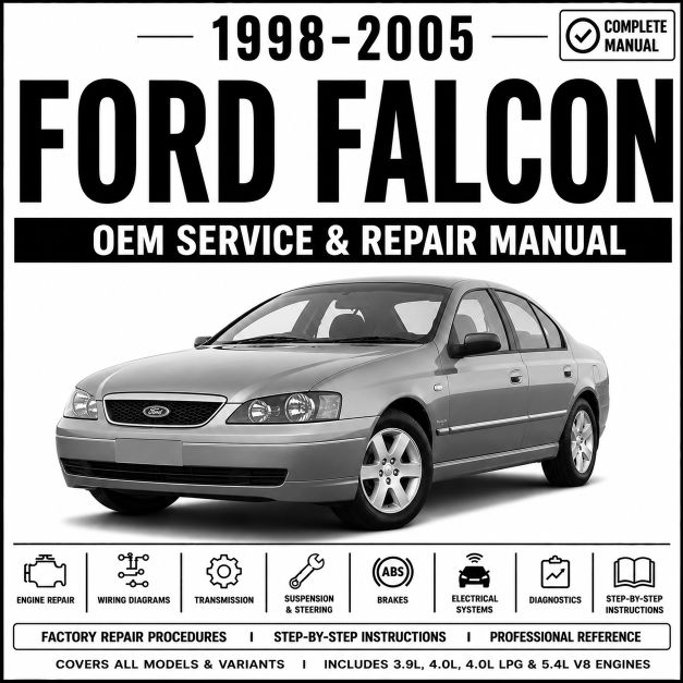
1998-2005 Ford Falcon Service and Repair Manual
Price: $36.99
Overview
This factory Service and Repair Manual for the 1998-2005 Ford Falcon AU, BA, and BF Mark I series provides comprehensive technical specifications, diagnostic procedures, troubleshooting information, and step-by-step repair instructions. It covers all major vehicle systems, powertrain variants, transmission options, and electronic control systems available for this model year range.
The manual includes complete mechanical repair procedures, electrical wiring diagrams, diagnostic trouble code (DTC) troubleshooting, transmission service information, braking system repairs, and body control module diagnostics.
Whether you are a professional technician, workshop owner, automotive student, or DIY enthusiast, this manual provides the information needed to diagnose, service, maintain, and repair the 1998-2005 Ford Falcon.
What you get;
✓ Genuine factory workshop manual
✓ Comprehensive diagnostic procedures
✓ Complete wiring diagrams
✓ Covers all major systems and components
Download via eManualOnline
You will be redirected to the official eManualOnline diagnostic archive. Your payment is securely processed on their encrypted network for instant download.
This 1998-2005 Ford Falcon Service and Repair Manual Covers
Engine and Drivetrain
- Intech 4.0L OHC I6 and Barra 182 4.0L DOHC I6 petrol engine overhauls and timing setups
- Barra 240T 4.0L DOHC Turbo I6 (XR6 Turbo) internal mechanical specifications
- Intech E-Gas and Barra E-Gas Dedicated LPG fuel system delivery, delivery lines, and mixer servicing
- 4.9L Windsor V8, 5.6L Windsor V8, and Barra 220 5.4L SOHC 3V V8 engine block assemblies
- Boss 260 and Boss 290 5.4L DOHC 4V V8 performance engine mechanicals and valve train procedures
- Sequential electronic fuel injection system diagnostics, throttle configurations, and dual VCT testing
- Engine cooling system specifications, radiator core replacements, and water pump overhauls
- Exhaust and emissions control troubleshooting, catalytic converters, and oxygen sensor loops
- BTR M93LE and M97LE 4-speed automatic transmission overhauls and electronic valve body diagnostics
- ZF 6HP26 6-speed automatic transmission service and fluid specifications (2004-2005 models)
- BTR T5 5-speed, Tremec TR-3650 5-speed, and Tremec T56 6-speed manual gearbox teardowns
- Live axle, non-independent rear suspension configurations, and leaf spring axle assemblies
- Double wishbone and Control Blade independent rear suspension (IRS) differential and half-shaft maintenance
Chassis and Suspension
- SLA front suspension and virtual pivot front suspension control arm and ball joint removal
- Multi-link Control Blade independent rear suspension setup and alignment shims
- Power steering rack and pinion pressure testing, pump seal replacements, and system bleeding
- Wheel alignment factory specifications, camber, caster adjustments, and toe tolerances
- Hub carrier assembly and wheel bearing press procedures
Braking Systems
- ABS hydraulic assembly diagnostic trouble codes and component location maps
- Traction Control System (TCS) and early Dynamic Stability Control (DSC) module testing
- Brake master cylinder, vacuum booster, and brake line bleeding sequence specifications
- Handbrake cable routing, center console actuator levers, and shoe linings adjustments
- Standard floating calipers and multi-piston performance brake disc rotor milling boundaries
Electrical and Wiring
- Complete factory electrical schematic maps and wiring harness connector pinouts
- SmartLock and SmartShield immobilizer anti-theft security module diagnostics
- Power distribution structures, engine bay fuse boxes, and cabin fuse panel identification
- Body Control Module (BCM) configurations, remote key fob adaptations, and locking actuators
- Interior Command Centre (ICC) audio and trip computer display multi-wiring patterns
- Reverse parking assist module circuitry and sonar sensor tone testing
Air Conditioning and HVAC
- Electronic Climate Control (ECC) manual and dual-zone logic circuits
- Blend door actuator shaft arm replacement procedures without complete dashboard disassembly
- R134a refrigerant system recharging capacities and high-low pressure diagnostic limits
- Heater core exchange, evaporator housing drainage, and blower resistor replacement
Body and Interior
- Interior cabin door trim panels, center floor consoles, and roof lining removal pathways
- Factory manual and multi-way power track driver seat frames and cushion repairs
- Radiator support panel alignment, exterior bumpers, and weather seal strip channels
- Electric power window regulator replacements and window track slide adjustments
- Supplemental Restraint System (SRS) diagnostic guidelines, clocksprings, and driver-passenger airbags
Diagnostics and Troubleshooting
- Ford Worldwide Diagnostic System (WDS) and Integrated Diagnostic System (IDS) pinpoint maps
- Data Link Connector (DLC) OBD2 port location and parameter ID (PID) scan data logging
- Fuel rail pressure checks, cylinder compression, and block leak-down testing metrics
- Systematic engine crank but no-start diagnostic test paths
Common Error Codes Covered
This manual provides diagnostic and repair procedures for thousands of Ford-specific fault codes, including:
Engine Codes
- P0171 / P0174: Fuel System Lean Bank 1 / Bank 2 (Intech and Barra intake manifold leak diagnostics)
- P0300 – P0306: Random / Individual Cylinder Misfires (ignition lead and coil pack testing schedules)
- P1381 / P1383: Variable Camshaft Timing (VCT) Over-Advanced / Over-Retarded
- P0420: Catalyst System Efficiency Below Threshold
- P1000: OBD On-Board Diagnostic System Readiness Test Incomplete
Transmission Codes
- P0705: Transmission Range Sensor Circuit Malfunction (PRNDL switch adjustments)
- P0731 / P0734: Gear 1 / Gear 4 Incorrect Ratio (BTR and ZF transmission clutch slip values)
- P1783: Transmission Over-Temperature Condition Indication
ABS and Chassis Codes
- C1145 / C1155: Wheel Speed Sensor Input Circuit Failure Front Right / Front Left
- C1277: Steering Wheel Angle Sensor 1 and 2 Circuit Malfunction (DSC calibration)
- C1445: Brake Accelerator Pedal Position Switch Circuit Failure
Network Communication Codes
- U1900: CAN Communication Bus Fault (Standard diagnostic cluster communication failures)
- U2514: Missing Vehicle Speed Message on CAN Communication Network
Body Control Codes
- B1313 / B1317: Battery Voltage High / Low (BCM charging circuit tolerance thresholds)
- B1352: Ignition Key-In Circuit Radio / Accessory Power Loop Mismatch
And thousands of additional diagnostic codes, test procedures, wiring diagrams, and repair instructions.
This manual is ideal for:
- Professional automotive workshops
- Independent repair garages
- Mobile mechanics
- Automotive technicians
- Vehicle owners performing DIY repairs
- Automotive training institutions
If you are troubleshooting, maintaining, servicing, or repairing a 1998-2005 Ford Falcon AU, BA, or BF Mark I, this is the factory workshop manual you need.
This Manual Applies to the followig model years;
Ford Falcon 1998
Ford Falcon 1999
Ford Falcon 2000
Ford Falcon 2001
Ford Falcon 2002
Ford Falcon 2003
Ford Falcon 2004
Ford Falcon 2005
Download the Complete Manual via eManualOnline
You will be redirected to the official eManualOnline diagnostic archive. Your payment is securely processed on their encrypted network for instant download.
No reviews yet. Be the first to review this product.
Returns accepted within 30 days of delivery. See our returns policy for full details.