Your Cart is empty
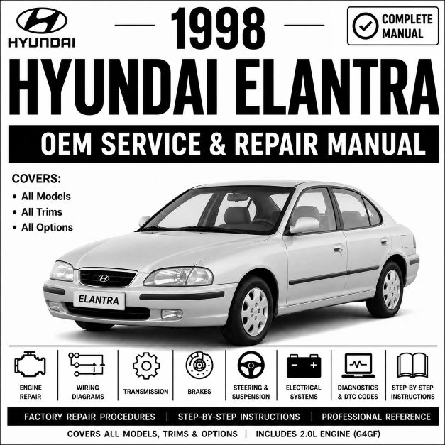
1998 Hyundai Elantra Service and Repair Manual
Price: $36.99
Overview
This factory Service and Repair Manual for the 1998 Hyundai Elantra provides comprehensive technical specifications, diagnostic procedures, troubleshooting information, and step-by-step repair instructions for all major vehicle systems fitted to this model year.
The manual covers the 1.8L and 2.0L 4-cylinder engines, 5-speed manual and 4-speed automatic transmissions, front-wheel drivetrain, suspension, braking systems, electrical systems, climate control, body components, and electronic control modules available on the 1998 Hyundai Elantra. It also includes complete factory wiring diagrams, diagnostic procedures, repair illustrations, torque specifications, and manufacturer-approved service procedures.
Where applicable, the manual also covers vehicle-specific technologies such as Multi-Port Fuel Injection (MPI), anti-lock brakes, dual front airbag systems, cruise control, and other factory-installed equipment available for this model year.
Whether you are a professional technician, workshop owner, automotive student, or DIY enthusiast, this manual provides the factory information required to diagnose, service, maintain, and repair the 1998 Hyundai Elantra.
What you get;
✓ Genuine factory workshop manual
✓ Comprehensive diagnostic procedures
✓ Complete factory wiring diagrams
✓ Covers all factory-installed systems and components
✓ We review every manual to ensure it's genuine and safe for download
Download via eManualOnline
You will be redirected to the official eManualOnline diagnostic archive. Your payment is securely processed on their encrypted network for instant download.
This 1998 Hyundai Elantra Service and Repair Manual Covers
Engine and Drivetrain
The manual includes complete repair procedures for the standard powertrain configurations available for the 1998 Hyundai Elantra, including:
- 1.8L DOHC Beta I Inline-4 Engine
- 2.0L DOHC Beta I Inline-4 Engine (Non-CVVT variant)
- 5-Speed Manual Transmission
- 4-Speed Automatic Transmission (A4BF1) w/ Overdrive
Coverage includes:
- Complete engine overhaul and cylinder head machining procedures
- Multi-Port Fuel Injection (MPI) fuel rail and injector cleaning specs
- Distributorless ignition system (DIS) dual-coil pack testing
- Engine cooling system, water pump, and thermostat replacements
- Lubrication system servicing and oil pan resealing
- Exhaust and emissions control diagnostics (including EGR, Catalytic Converter, and EVAP systems)
- Timing belt replacement, mechanical tensioner spring setup, and timing mark alignment
- Manual transmission overhaul, clutch disc, and pressure plate replacement
- Automatic transmission torque converter clutch (TCC) adjustments and valve body schematics
- Front differential, driveshaft, and constant velocity (CV) axle servicing
Chassis and Suspension
Coverage includes the specific front-wheel-drive independent suspension setups fitted to the vehicle:
- Front MacPherson strut suspension and coil spring repair procedures
- Rear independent dual-link strut suspension repair procedures
- Hydraulic power steering rack and pump mechanical troubleshooting
- Four-wheel alignment factory specifications
- Front and rear wheel hub and bearing replacement
- Suspension stabilizer bar link and control arm bushing inspection
Braking Systems
The manual includes repair procedures for the standard hydraulic safety braking configurations:
- Front ventilated disc and rear drum braking systems
- Anti-lock Braking System (ABS) hydraulic modulator troubleshooting
- Brake proportioning valve mechanical test procedures
- Brake component inspection, shoe/pad replacement, and drum/rotor machining
- Brake master cylinder overhaul and manual system bleeding procedures
- Mechanical cable-operated handbrake adjustments
Electrical and Wiring
Coverage includes every factory electrical layout available on the 1998 model year:
- Complete factory wiring diagrams and circuit ground tracking
- Alternator charging output, starter motor circuit, and 12V battery test procedures
- Passenger compartment Junction Block and under-hood Relay Box schematics
- Engine Control Module (ECM) and Transmission Control Module (TCM) diagnostics
- Power window switches, power door locks, and power sunroof motor mechanics
- Factory AM/FM cassette head unit wiring layouts and speaker polarities
- Instrument cluster mechanical-electronic gauge testing (speedometer, tachometer, fuel level)
Air Conditioning and HVAC
Coverage includes:
- Manual climate control slide levers or dial assembly diagnostics
- Air conditioning compressor clutch assembly, field coil, and pulley replacement
- R134a refrigerant system capacity and manifold gauge servicing procedures
- Heater core extraction and air blend door flap replacement
- Blower motor resistor block speed step diagnostics
Body and Interior
Coverage includes:
- Interior dashboard pad, center console, and door panel trim removal
- Manual and power mirror assembly replacement
- Seat belt pretensioners, mechanical retractor anchors, and bucket seat frame rails
- Power locks and remote keyless entry module diagnostics (where equipped)
- Supplemental Restraint System (SRS) front dual airbag safety precautions
- Station wagon rear tailgate strut cylinders and sedan trunk lid linkage alignment
Diagnostics and Troubleshooting
The manual includes complete manufacturer-approved diagnostic procedures, including:
- OBD-II Diagnostic Trouble Code (DTC) lookup
- Factory diagnostic flowcharts and pinpoint testing workflows
- Hi-Scan diagnostic tool data link connection procedures
- Live data stream parameter interpretation (O2 sensor voltages, fuel trims, MAF data)
- Engine sensor voltage and resistance testing specs (TPS, CKP, CMP, ECT)
- Connector pinouts and harness end views
Common Error Codes Covered
This manual includes diagnostic procedures for thousands of manufacturer-specific and generic Diagnostic Trouble Codes (DTCs).
Engine Codes
- P0300 — Random/Multiple Cylinder Misfire Detected
- P0340 — Camshaft Position Sensor Circuit Malfunction
- P0420 — Catalytic Converter Efficiency Below Threshold (Bank 1)
- P0441 — EVAP System Incorrect Purge Flow
- P0500 — Vehicle Speed Sensor Malfunction
Transmission Codes
- P0700 — Transmission Control System Malfunction (MIL Request)
- P0715 — Input/Turbine Speed Sensor Circuit Malfunction
- P0734 — Gear 4 Incorrect Ratio
ABS and Chassis Codes
- C1201 — Wheel Speed Sensor Front-LH Invalid/Failed Signal
- C1204 — Wheel Speed Sensor Rear-LH Open or Short Circuit
- C1604 — ABS Control Module Hardware Error
Network Communication Codes
- U0001 — High-Speed CAN Communication Bus Malfunction
- U0100 — Lost Communication with ECM/PCM
- U0101 — Lost Communication with TCM
Body Control Codes
- B1111 — Airbag Control Module Battery Voltage High
- B1326 — Driver-Side Airbag Sensor Circuit Short to Ground
- B1402 — Driver Power Window Switch Circuit Malfunction
The manual also includes thousands of additional diagnostic codes, wiring diagrams, test procedures, manufacturer diagnostic charts, and repair instructions.
Fuse Box Diagram
Locate every fuse and relay installed on the 1998 Hyundai Elantra using complete factory layouts.
Coverage includes:
- Engine Compartment Fuse Box (Relay & Fusible Link Box) situated next to the air cleaner box
- Passenger Compartment Fuse Panel (Junction Block) located on the lower left driver’s side dashboard area
- Amperage ratings (10A, 15A, 30A, 50A fusible links)
- Relays (Fuel pump, horn, A/C clutch, starter, and main ECU relays)
- Circuit paths and internal terminal tracing
Wiring Diagrams
The manual includes complete factory electrical system schematics covering every circuit on the vehicle.
Coverage includes systems such as:
- Beta I Engine management, ignition coils, and fuel delivery circuits
- Alternator charging and starting system circuitry
- High/low beam headlights, turn signals, and hazard lights
- ABS module power and wheel speed sensor routing
- Manual HVAC blower motors and heater paths
- Supplemental Restraint System (SRS) deployment circuits
- ETACS (Electronic Time and Alarm Control System) body automation
Serpentine Belt and Timing Belt Routing Diagrams
The manual includes:
- Accessory drive belt routing paths for the alternator, power steering pump, and A/C compressor
- Timing belt replacement procedures, tensioner spring setup, and top-dead-center (TDC) alignment marks
- Drive belt tension inspection values and deflection specs
- Scheduled factory belt inspection and replacement intervals
- Special service tools for crankshaft pulley holding
Torque Specifications
The manual provides complete factory torque values for major components:
- Cylinder head bolts (torque-to-yield tightening angle specs)
- Connecting rod caps and main bearing bolts
- Flywheel (Manual) or Flexplate (Automatic) fasteners
- Front strut tower bolts and lower control arm ball joints
- Front brake caliper mounting bracket bolts and slider pins
- Hub assembly wheel lug nuts
This manual is ideal for:
- Professional automotive workshops
- Independent repair garages
- Mobile mechanics
- Automotive technicians
- Vehicle owners performing DIY maintenance and repairs
- Automotive training institutions
Whether you need to replace a simple cabin fuse or completely rebuild the engine, this document delivers the verified factory specs to complete the job cleanly and safely.
Download the Complete Manual via eManualOnline
You will be redirected to the official eManualOnline diagnostic archive. Your payment is securely processed on their encrypted network for instant download.
No reviews yet. Be the first to review this product.
Returns accepted within 30 days of delivery. See our returns policy for full details.